About the Class
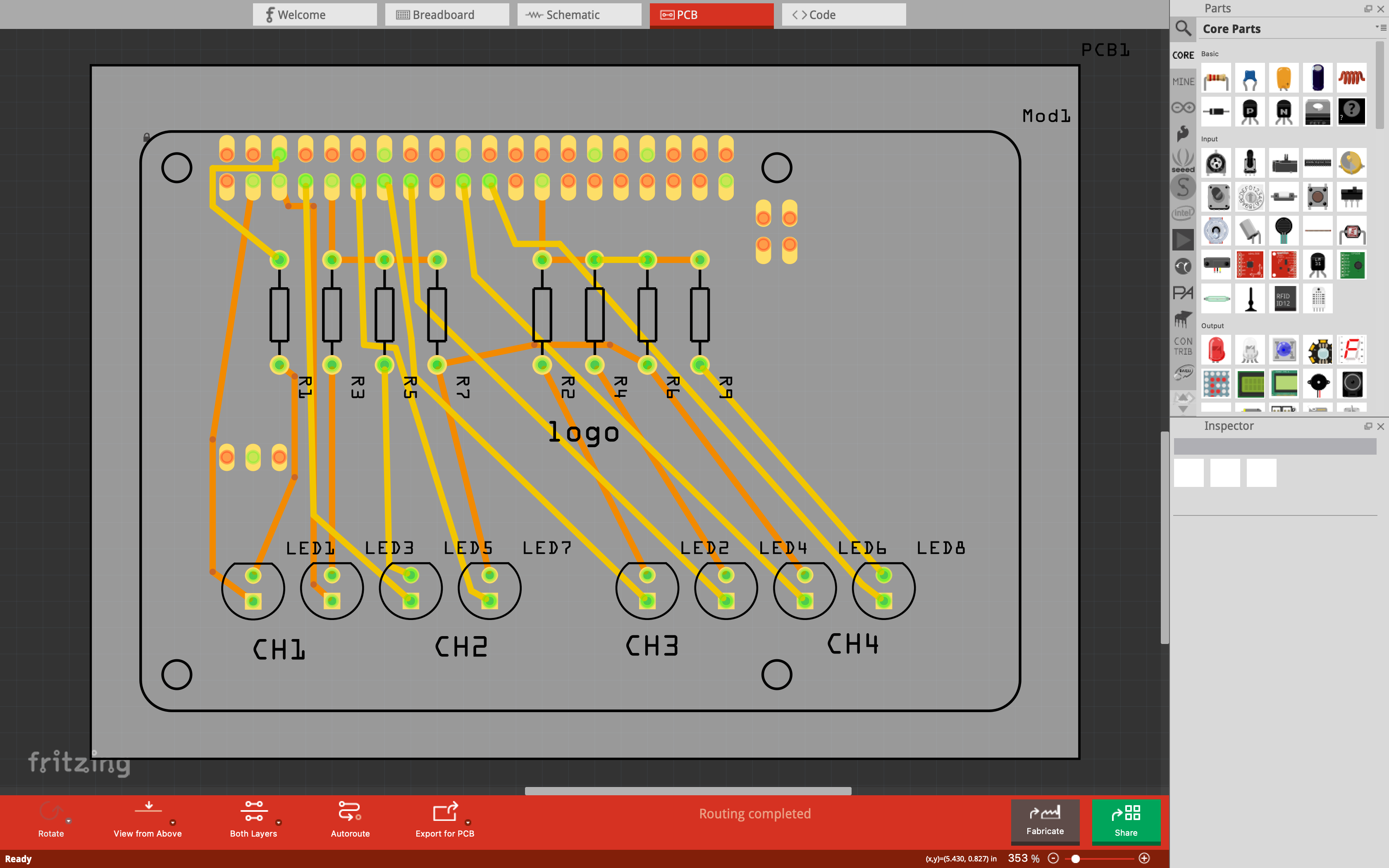
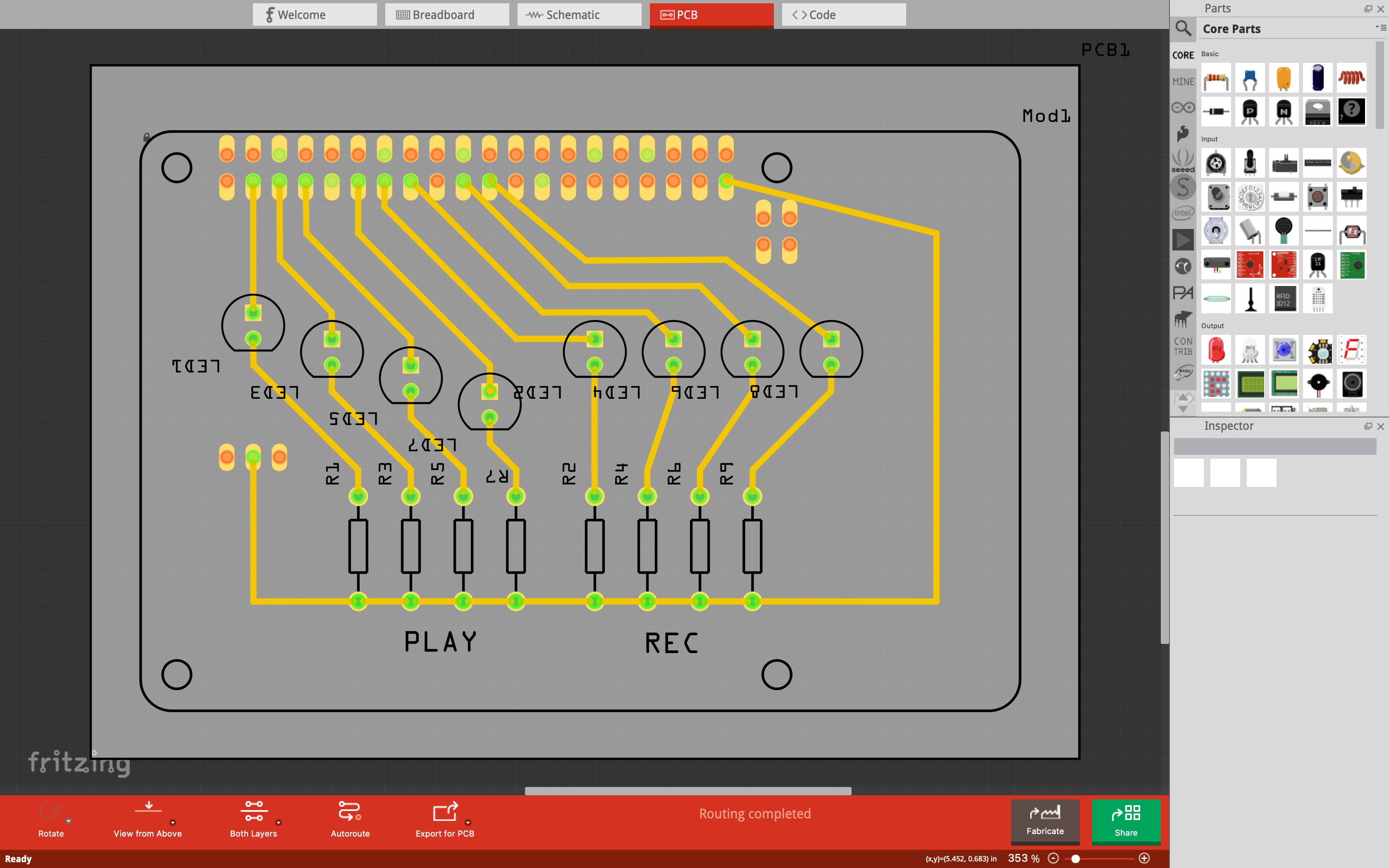
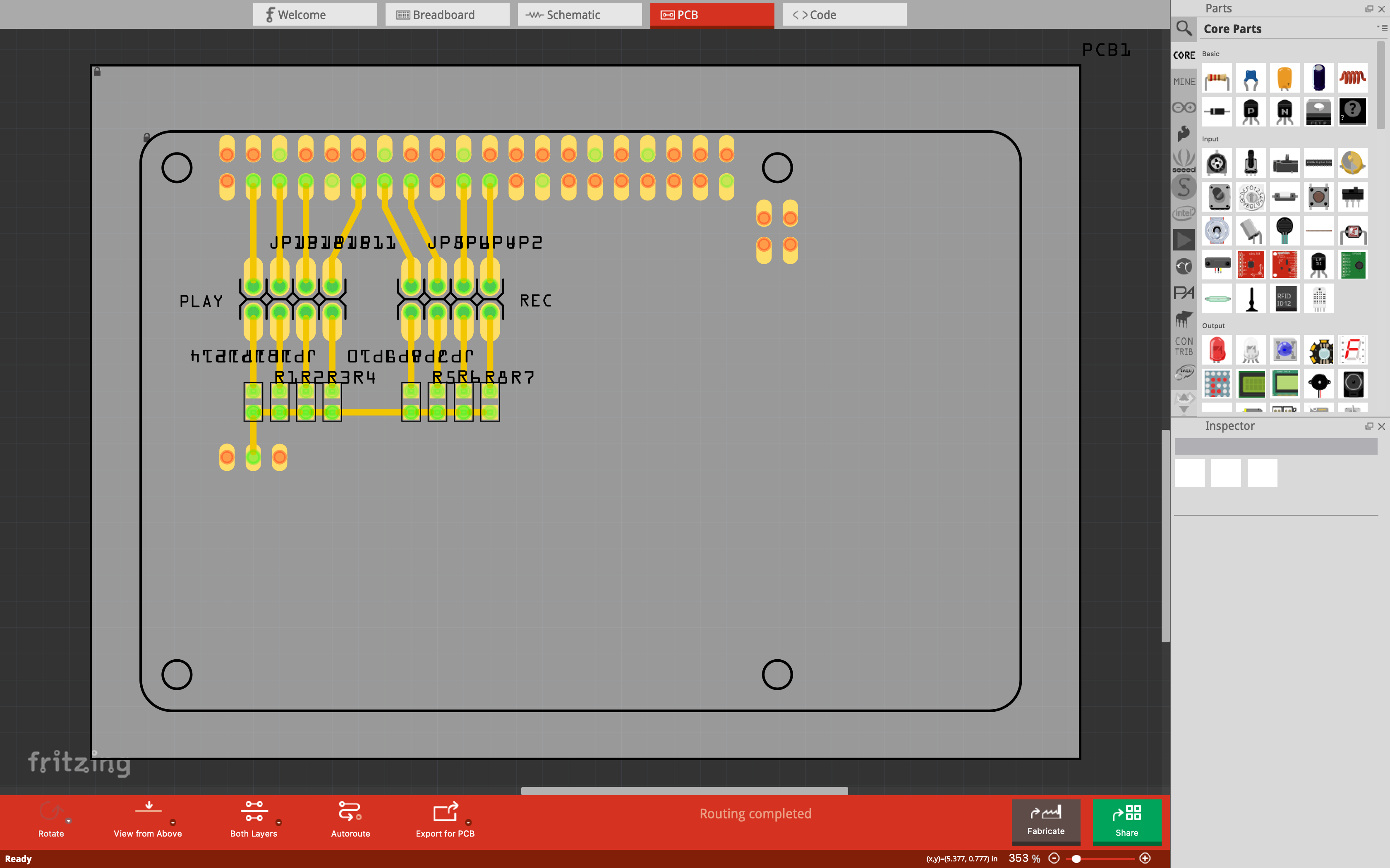
In this class we learned how to use KiCAD to design our own PCBs and how to mill them. Consequentially, below there are three iterations of the loop station shield for the Raspberry Pi 4, simplifying the circuitry and finally using surface-mount components (SMDs) to miniaturize the form factor.


Further Links
components
ribbon cable
IDC connector
button
switch
resistor: I=V/R
values
capacitor: C = Q/V, I = C dV/dt
unpolarized
polarized
crystal, resonator
inductor: V = L dI/dt
diode: current from anode to cathode
PN
Schottky
Zener
LED
transistor
bipolar: collector, emitter, base current gain
mosfet: source, drain, gate resistance
battery, regulator, DC-DC converter
op-amp: differential gain, negative feedback
microcontroller
sensors
actuators
circuits
Kirchoff's laws: sum current at node, voltage around loop = 0
power: P = I2R = IV
EDA
hierarchical, parametric drawing
packages, footprints, libraries
schematic entry, component placement, (auto)routing, simulation, fabrication
design rules
routing layers, power planes, ground pours
drawing
drafting tape
Tinkercad
Virtual Breadboard
Fritzing
LibrePCB
EasyEDA
gEDA
Lepton EDA
KiCad
BOM
video
Eagle
Fusion 360
Altium
Circuit Maker
libraries
Digi-Key
SnapEDA
Ultra Librarian
DesignSpark
library.io
OrCAD
Cadence
Synopsys
Mentor
Tanner
Magic
SPICE
LTspice
ngspice
gSpiceUI
WRspice
Gnucap
Qucs
Oregano
Multisim
Falstad
Verilog
VHDL
kokompe
kokopelli
frep.py
frep-C.py (pcb.py, video, Gerber) frep_gpu.py
SVG-PCB
test equipment
regulated power supply, digital multimeter, oscilloscope, logic analyzer, mixed signal
assignment
group project:
use the test equipment in your lab to observe the operation
of a microcontroller circuit board
individual project:
redraw an echo hello-world board,
add (at least) a button and LED (with current-limiting resistor)
check the design rules, make it, and test that it can communicate
extra credit: simulate its operation