Fabricating an Arduino Uno Shield
Designing the PCB
The function of the PCB was to multiply the 5V and GND pin outputs for the Arduino UNO Rev3 in the context of our Fab Challenge 4 (full documentation here and on Github). This was necessary to provide an apt amount of available headers for the 12+ control units that will be connected to that single Arduino. After working with Fritzing before in Week 6 (Electronics Design), I gave it another shot but was (again) disappointed by the UX and lack of control over some critical parameters, such as trace width. Then I switched to Illustrator, which is much more bare-bones (because it doesn't offer any kind of presets), but allows an unprecedented control over everything. It's important to note that this is also precisely the reason why it doesn't prevent you from making critical mistakes, such as defining a prohibitively narrow clearance for the 1/64" drill or just simply setting the wrong design ratio overall. Additionally, I designed the board in an inverted way for the female headers to be soldered from the bottom (more on that below), so the design was actually flipped along its horizontal axis. I assume this is could have been another error-prone step in the design process.
Find the design files here
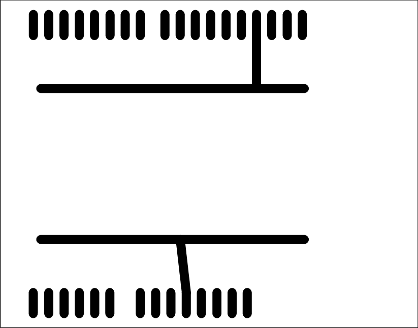
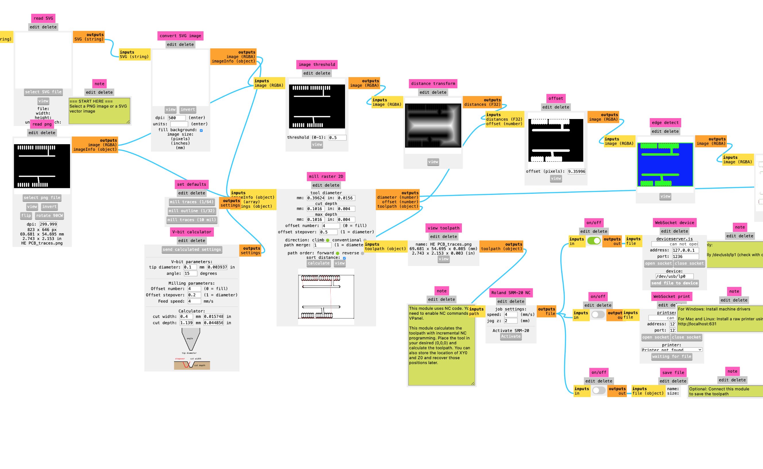
PCB traces PNG (left) and calculating process in Mods (right).
Milling the PCB
Gladly, I managed to avoid all of these pitfalls and quickly managed to finish the design in a short time frame. After exporting the files as PNGs (important: in exactly the same pixel aspect ratio!), I used the Community Edition of MIT's ModsProject to calculate the mill traces from the PNG source and convert them into the proprietary format of the Roland SRM-20 mill. The parameters used in the design and milling process were:
Trace mill: min. 1/64"
Outline mill: 1/32"
Minimal trace width: 0.35mm
Trace clearance: 0.4mm
Hole diameter: 1mm
Find the PCM milling files here
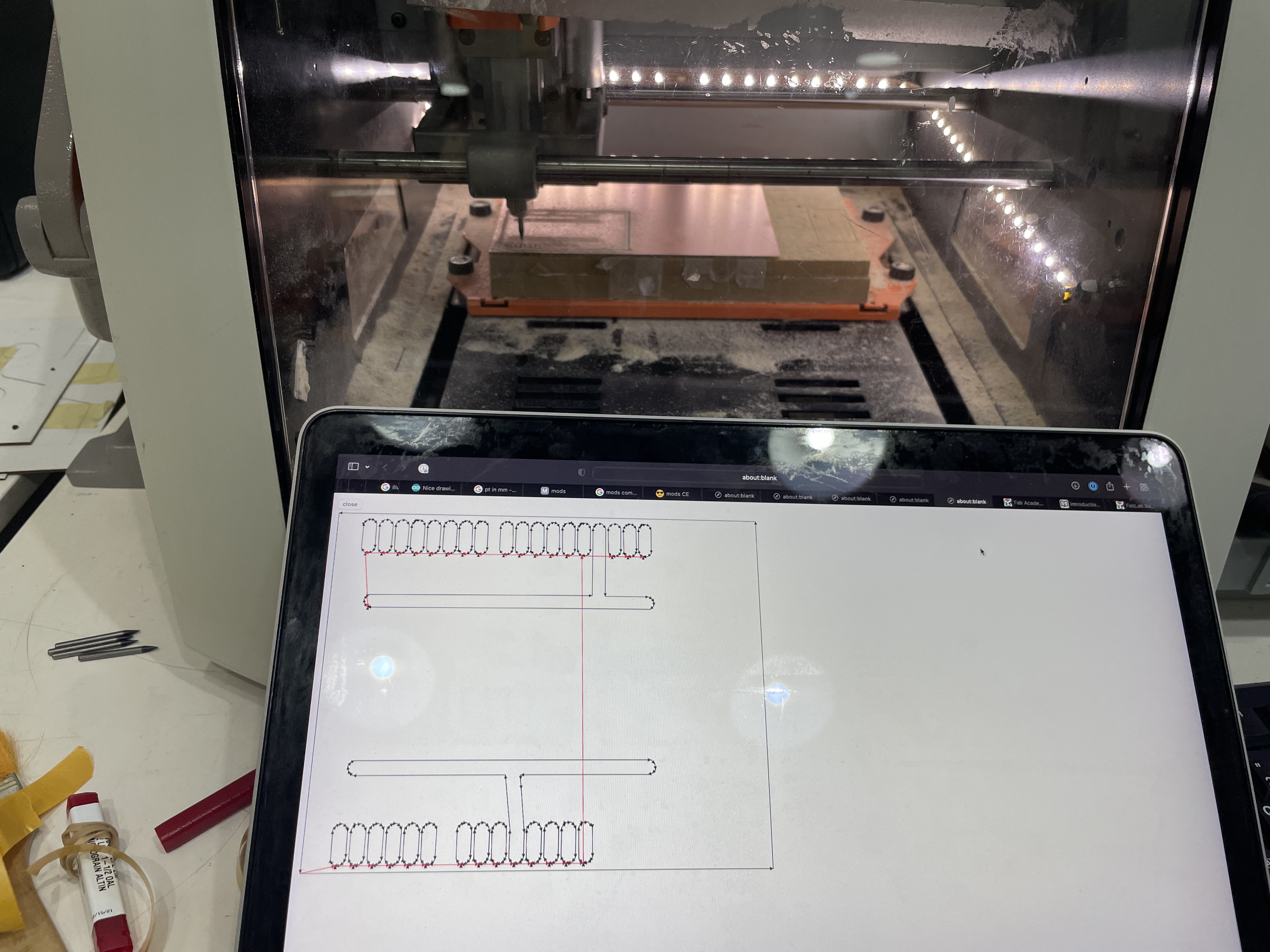
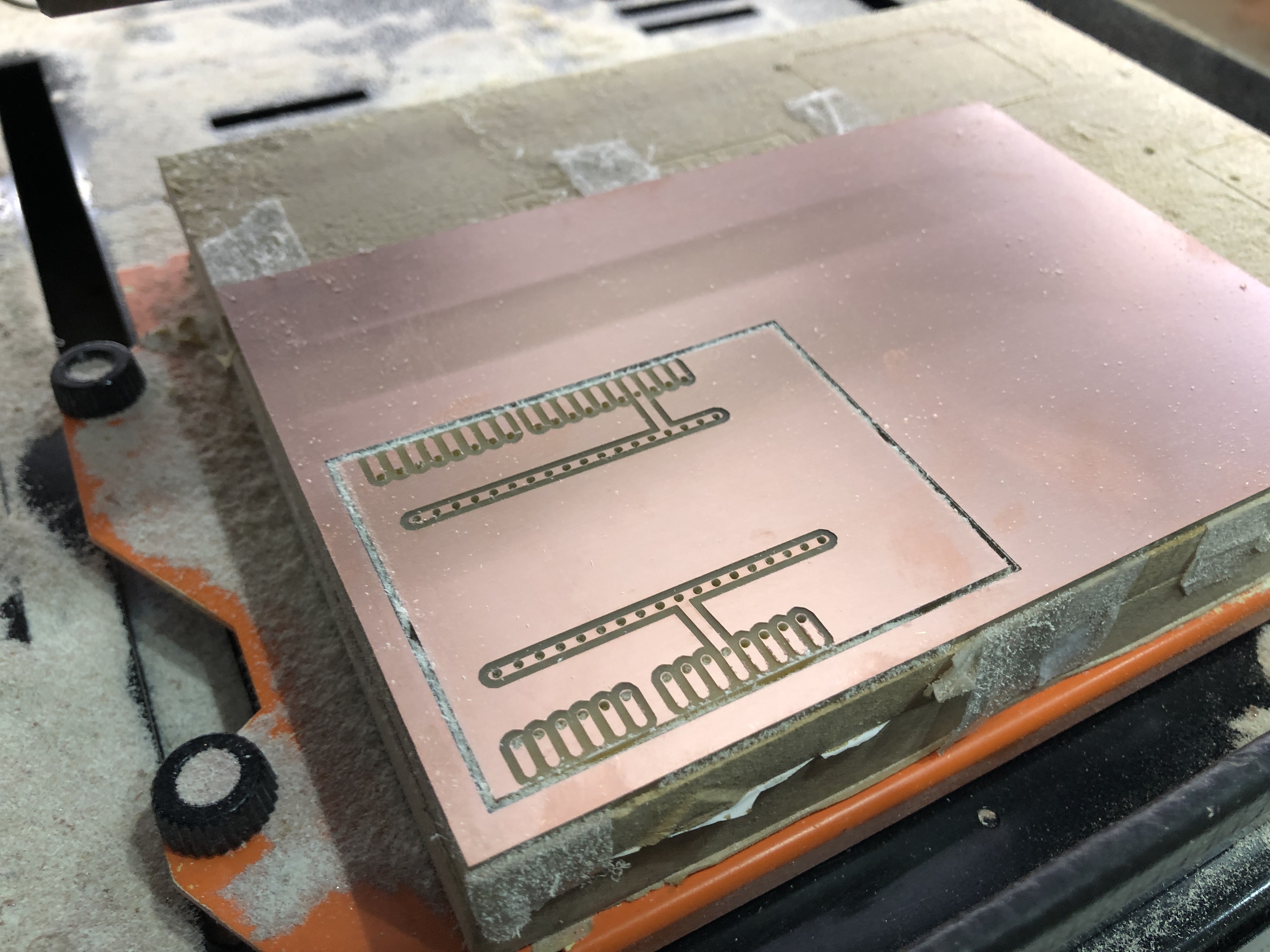
Milling during process (left) and the final milled outcome (right).
Soldering the PCB
Soldering the PCB was an interesting process due to the fact that the board had been intentionally designed in an inverted fashion: Through-holes were milled to receive female header pins to be soldered on the milled side directly on the contact points. This way, the visible side of the PCB is actually the 'back' of the board, showing only the substrate. The lower side (the milled side of the board), featured contact points for male header pins to be soldered directly on top without any through-holes. This way, the whole design was able to be executed with a single-side PCB, even though it features more than 100 headers (102 to be precise) on two sides of the board. Consequently, the soldering took almost two hours to complete. The outcome is nothing spectacular pr fancy, but the certainly our group is proud of.
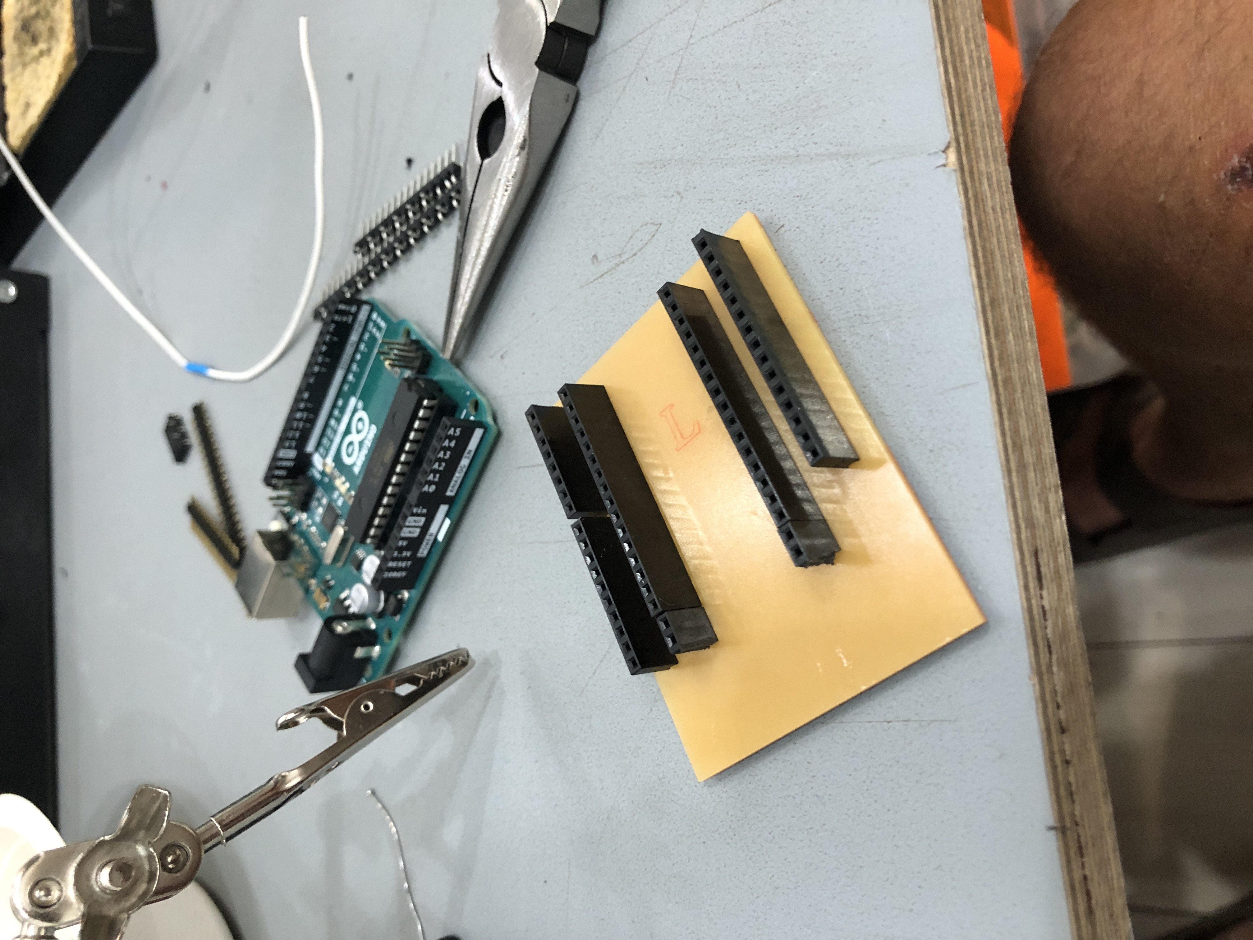
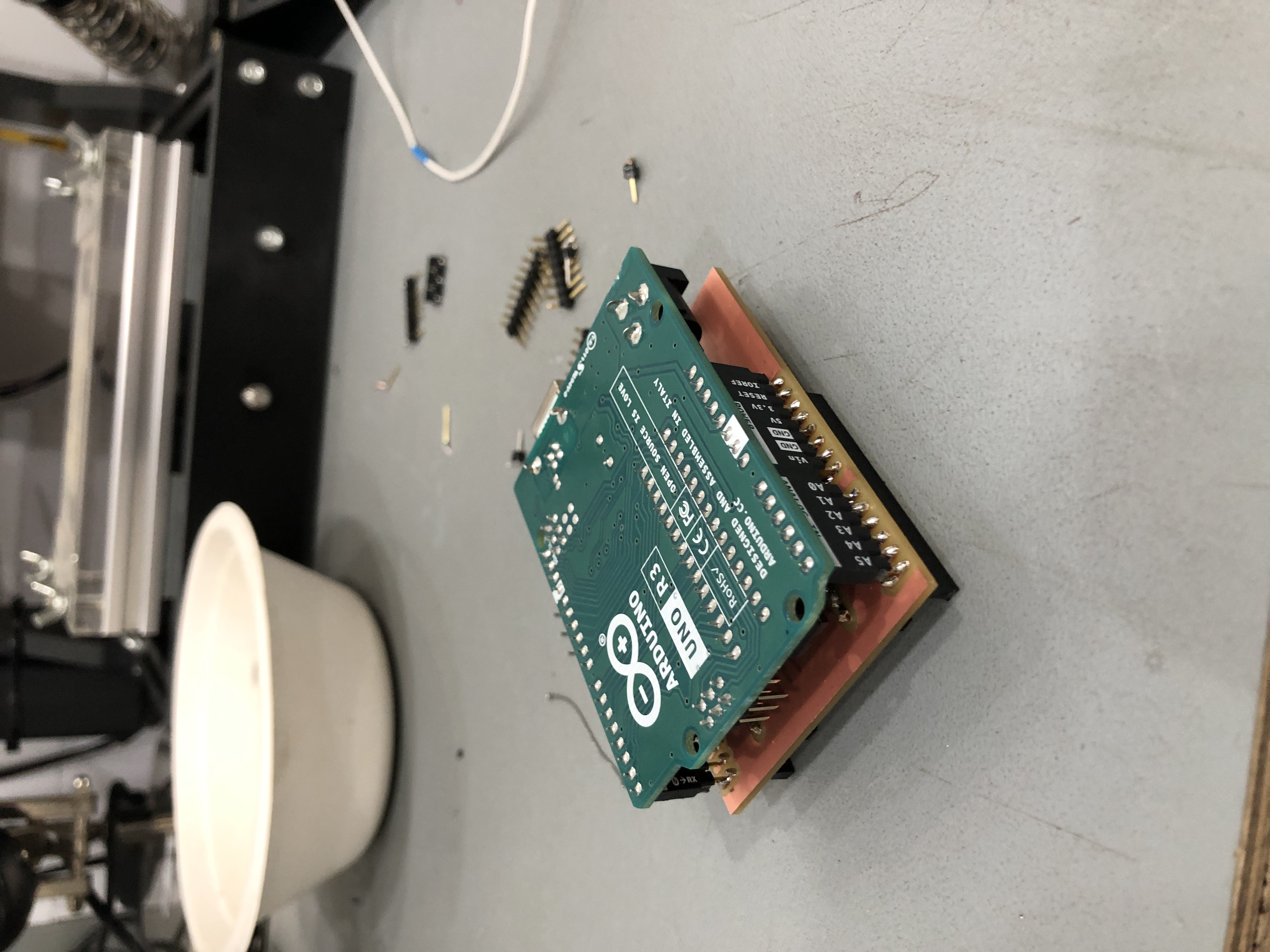
Soldering during process (left) and the final soldered outcome, showcasing the male headers plugging into the Arduino (right).
Using the PCB
As simple the PCB is in its design, as effective it is in its use. Over the last two days, we managed to reduce the amount of circuitry on the breadboard almost completely and move everything to our Arduino shield. As mentioned above, this is not the most sophisticated design, but its incredibly effective and we were able to manufacture it in less than five hours – including design, milling and soldering.
The next evolutionary step is to redesign the board in order to offer integrated circuits for the potentiometers and buttons (including pull-up resistors) and offering each one of those as a JST or Grove connector style plug. This would effectively be comparable to a custom and enhanced Arduino Grove shield and offer a comparable plug-and-play functionality. For this step to be reached we need to settle on the exact number of connected potentiometers, buttons, pressure sensors and capacitive touch sensors. When or if we get to that point, this post will be updated.
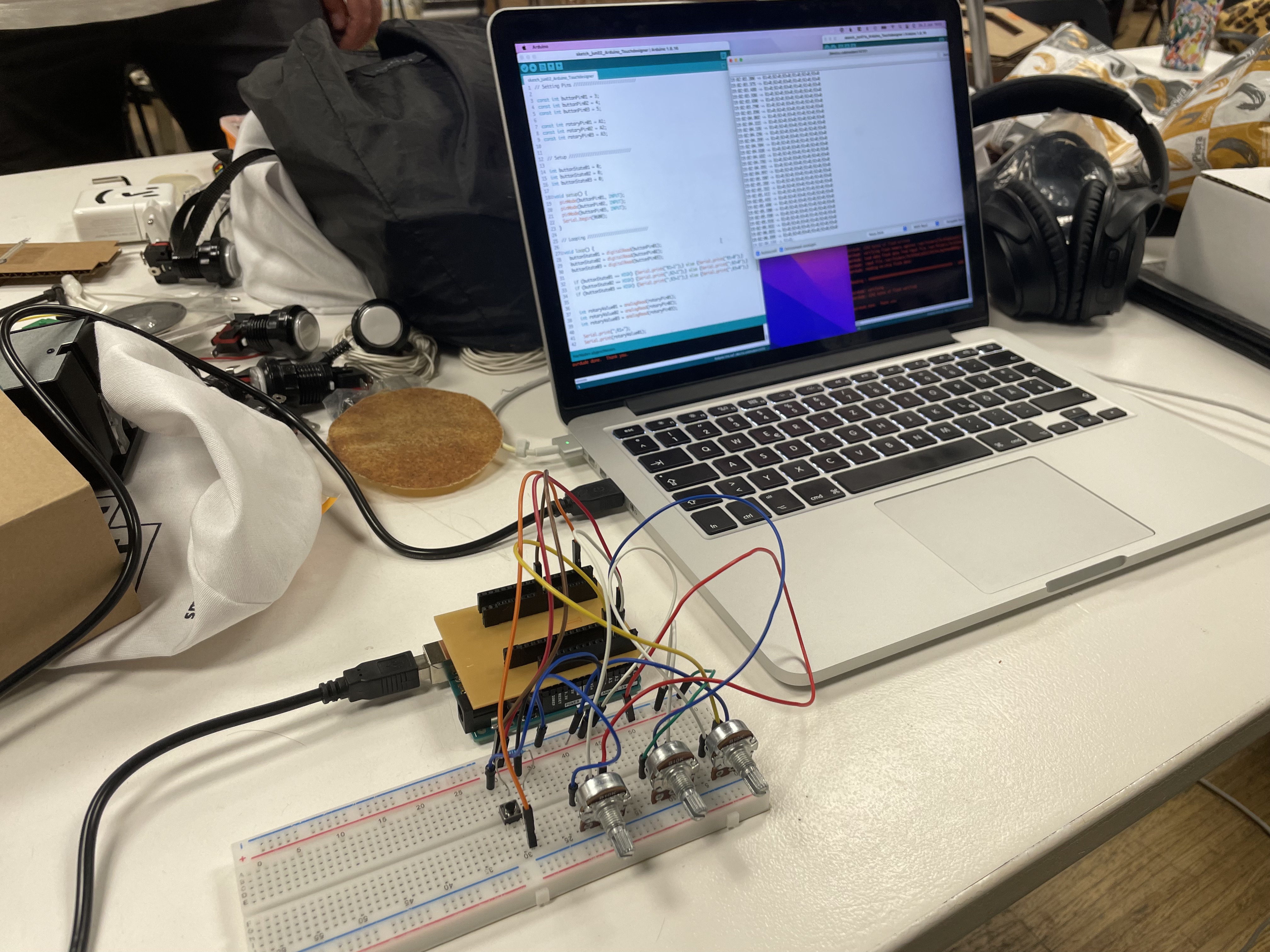
Beginning to use the shield in order to phase out the breadboard circuitry.
Fabricating a Second Arduino Shield
In order to iterate in the proof of concept shown above, we tackled the challenge to introduce a new connector standard between our Arduino shield and the eight control units. After evaluating different solutions, among them MOLEX and Grove connectors, and weighing them agains their availability, price and open-source qualities, we settled on 3-pole 3,5mm standard headphone jacks. This allowed us to quickly purchase the needed quantity of components needed for the PCB fabrication, the controllers and long connecting wires. The drawback was that the sequential nature of the connector presents a constant risk of shorts. This is why the leading credo with this solution was: Never hot plug!
To integrate the connector standard into our project, we redesigned the Arduino shield used in Fab Challenge IV. After using the wrong pins on the eight surface mounted female 3,5mm headphone jacks, we redesigned the PCB a third time to allocate the correct connections. More impressions below.
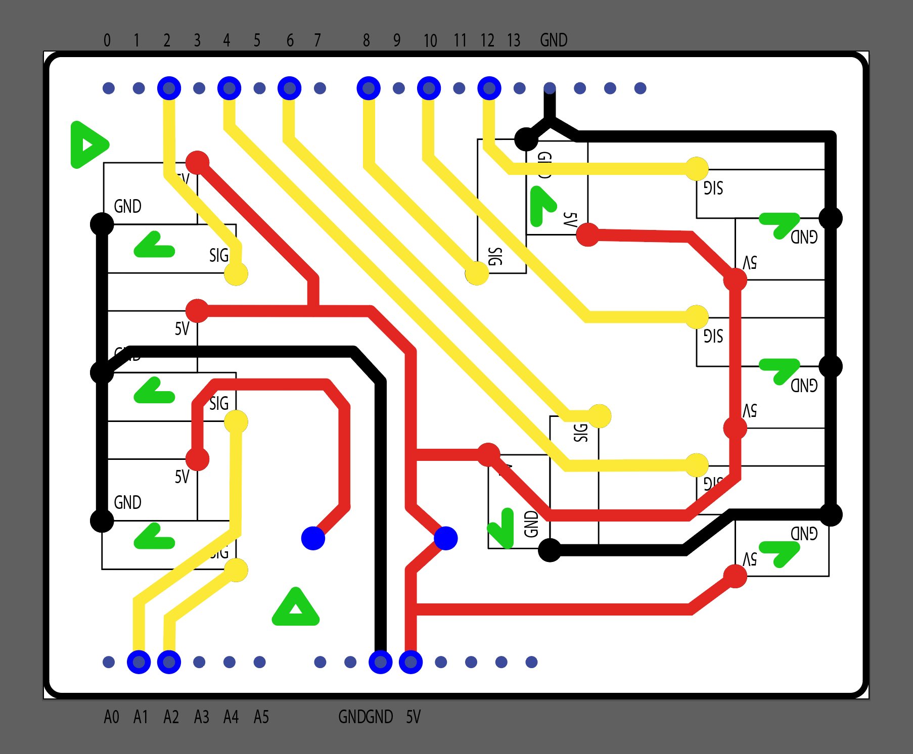
Second PCB design including eight surface mounted female 3,5mm headphone jacks – unfortunately using the wrong pins...
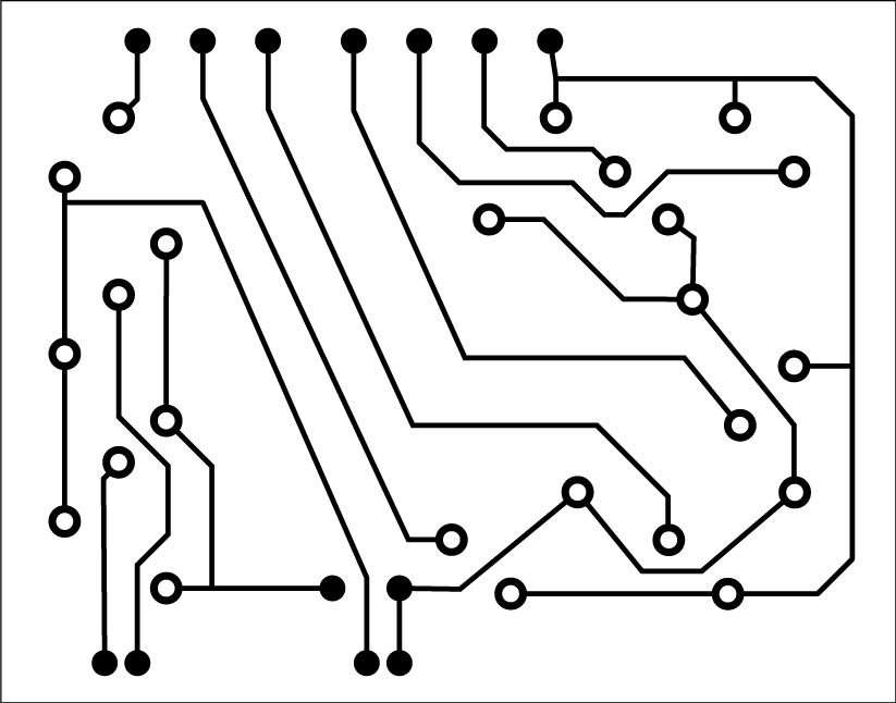
Correcting the previous mistakes, using the right pins on the headphone jacks SMDs, shown here as black and white traces ready to be milled. Notice the minimal 0,4mm trace width.
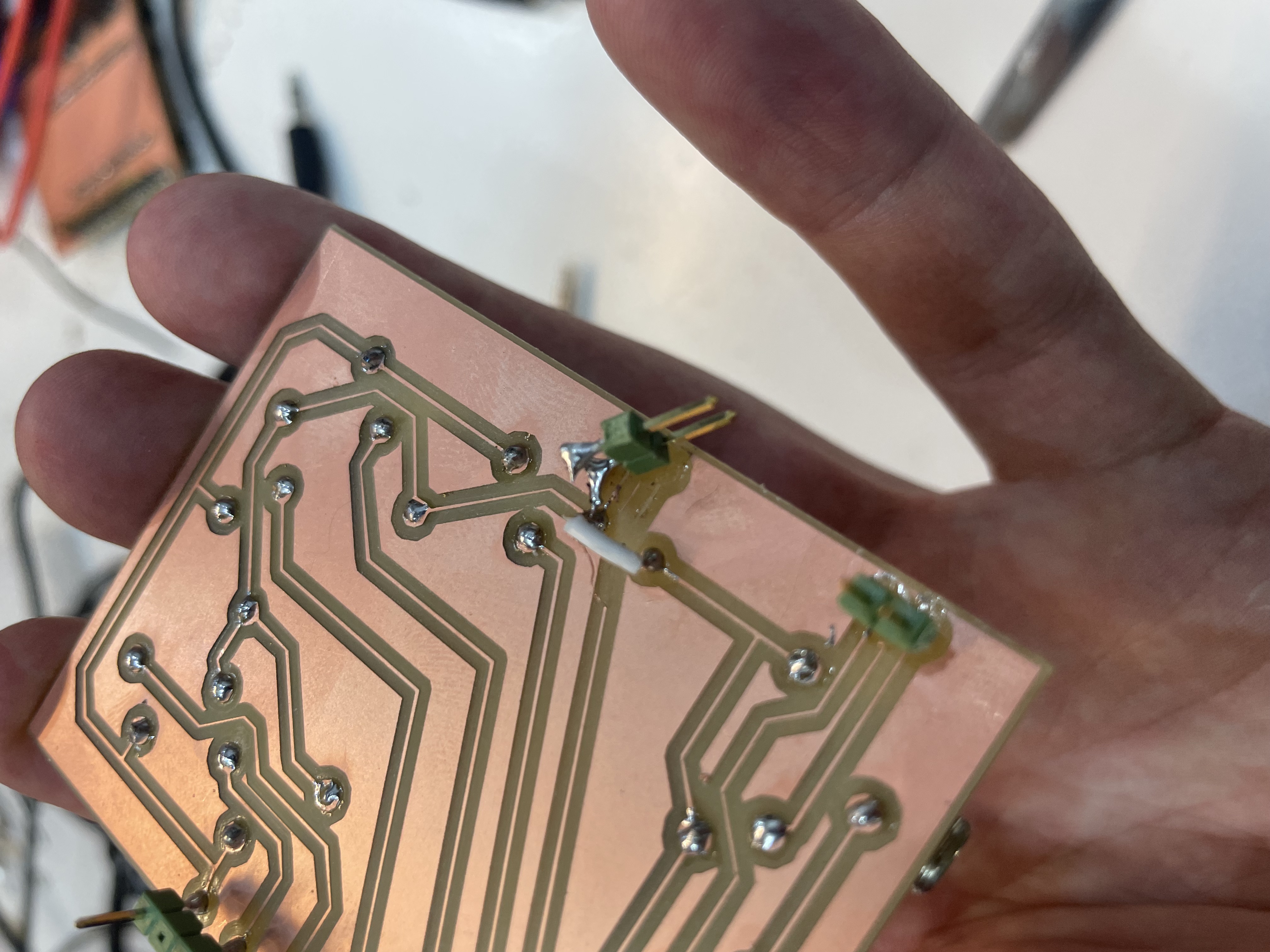
Left: Due to the minimal trace width, we pulled off the copper traces off the substrate after soldering two male pins onto it. Right: Mitigating the problem via two cut jumper wires, which short the necessary traces at another point of the PCB.
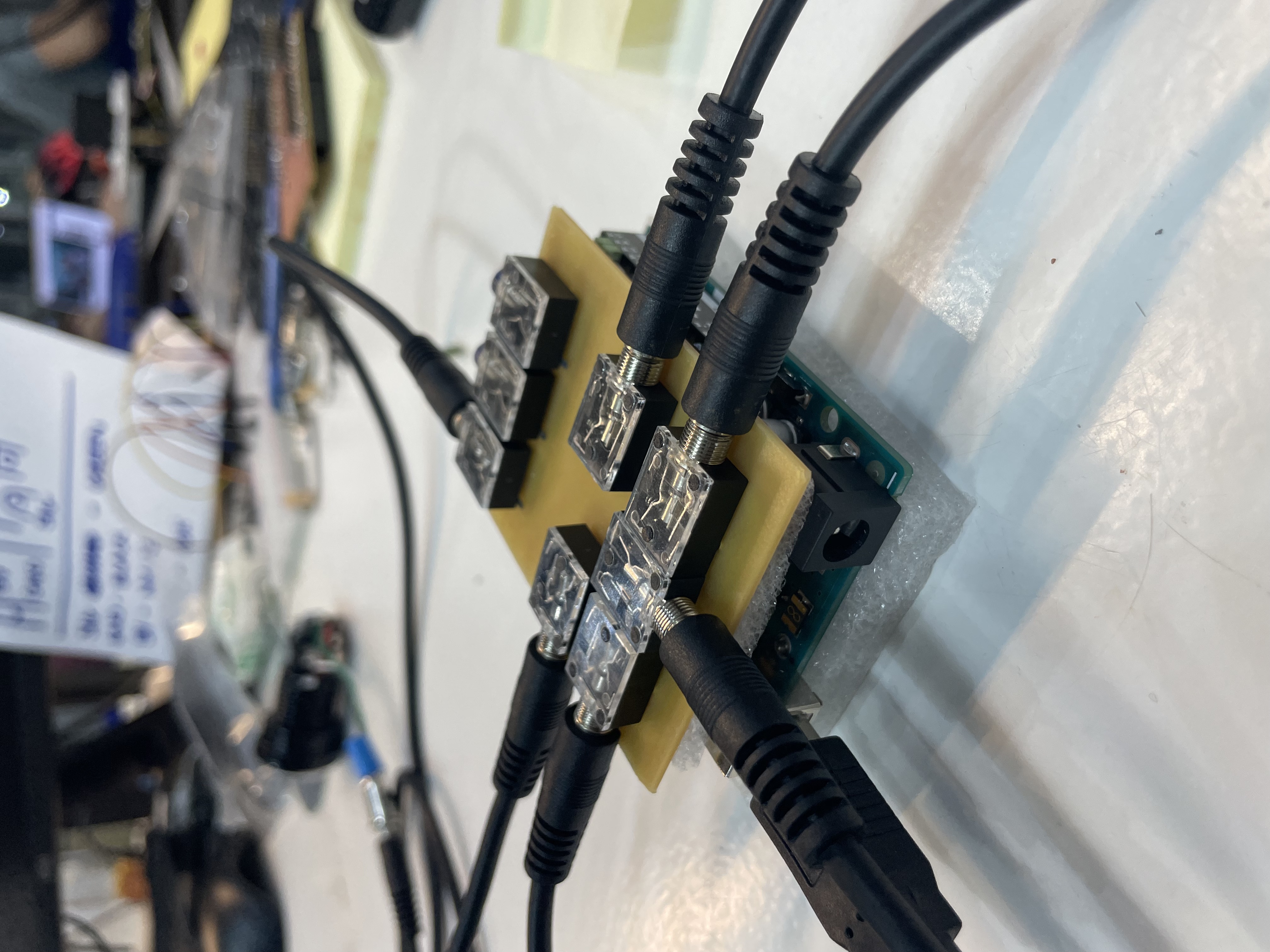
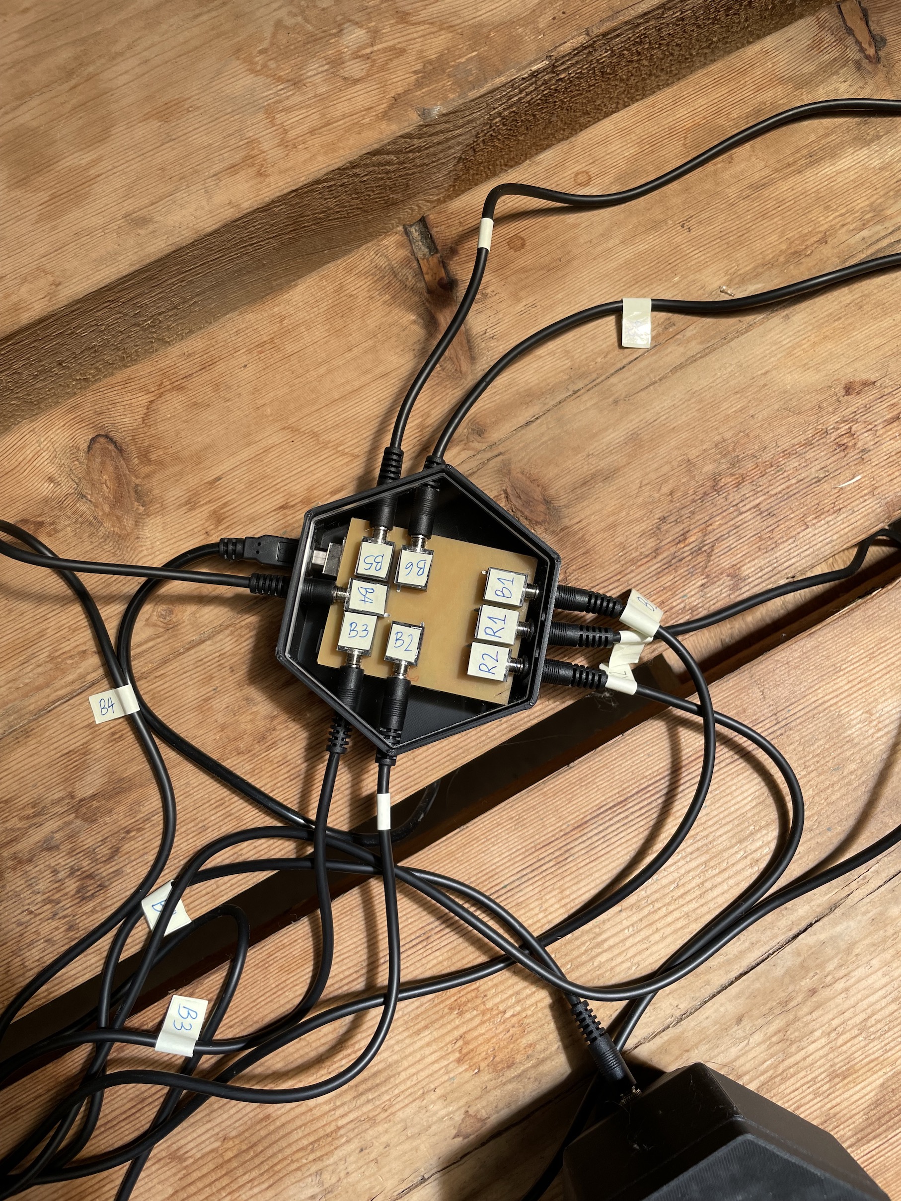
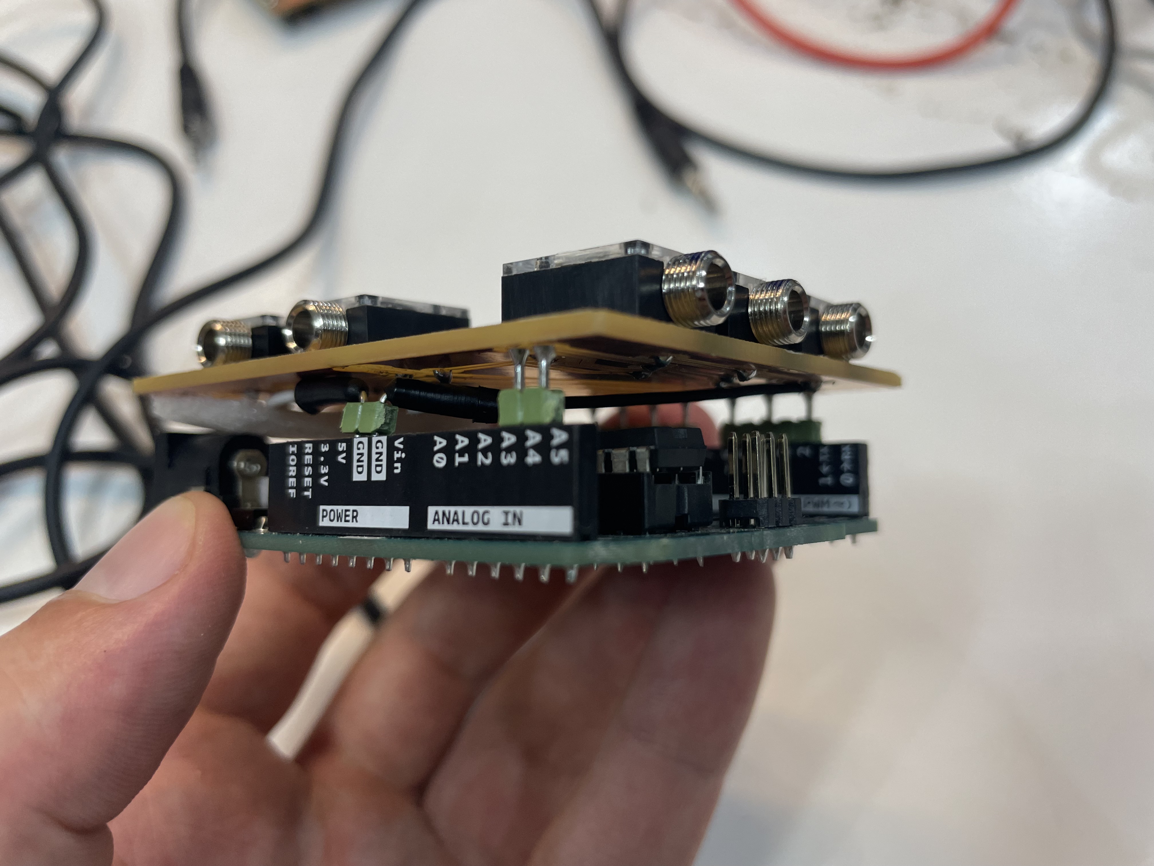
Left: The final PCB after soldering the headphone jacks. Right: The central unit in its final 3D printed case including an acrylic cover.
Further Links
Output Devices
electrical safety
~1 mA: OK
~10 mA: shock, contraction
~100 mA: fibrillation
body: M ohm external, k ohm internal
dielectric breakdown: ~kV/mm
supply capacitors
inductive flyback
protection diodes
connector polarization, orientation
protection
power
USB
supplies
switching, linear, regulated
supercapacitor
batteries
LiPo
charge controller
storage
wireless
current measurement
supply regulation
sense resistor
magnetic field
inductance
RGB LED
current limiting
PWM
hello.RGB.45
board
components
traces
interior
C
makefile
video
pinouts
pixels
lights
wires
LEDs
diode drop, series-parallel
MOSFET
N, P
floating gates
gate resistors
BJT, BiCMOS, IGBT
hello.LEDs.t412
board
components
traces
interior
hello.LEDs.t412.ino
video
thermal runaway
eye safety
LED
array
Charlieplexing
hello.array.44
board
components
traces
interior
C
makefile
video
hello.array.44.2
board
components
bottom
vias
top
interior
C
makefile
video
displays
LCD
HD44780
library
hello.LCD.44
board
components
traces
interior
C
makefile
video
I2C
PCF8574
library
hello.I2C.t1614
hello.LCD.I2C.ino
video
OLED
SSD1306
library
library
scripts pinout
hello.SSD1306.45
board
components
traces
interior
C
makefile
video
TFT
ILI9341
library
hello.ILI9341.SW.D21E
board
components
traces
interior
video
hello.ILI9341.HW.D21E
board
components
top
bottom
holes
interior
video
ST7735
video
E Ink
modules
video
RS170, NTSC, PAL, SECAM, VGA
75 ohm impedance
hello.video.44
board
components
traces
interior
C
makefile
video
SPI
TVout
thinner client
color
speaker
DAC, PWM
hello.speaker.45
board
components
traces
interior
C
makefile
video
wavetable
audio
synthesis
low-pass filter
class D amplifier
solenoid
DC motor
H-bridge
A4950
TB67H451FNG,EL
hello.H-bridge.44
board
components
traces
interior
C
makefile
video
Dual H-bridge
DRV8847
torque, power, efficiency, gearing
vibration
servo motor
50 Hz ~1-2 ms PWM
(dis)continuous rotation
ATtiny412
hello.servo.t412
board
components
traces
interior
hello.servo.t412.ino
hello.servo-registers.t412.ino
video
ATSAMD11C
hello.servo-D11C
board
traces
interior
Gerber
top copper
solder mask
silkscreen
outline
ATtiny44
hello.servo.44
board
components
traces
interior
ZLDO1117
hello.servo.44.1
board
components
traces
interior
LM2940
C (hardware PWM)
makefile
C (two-channel, software PWM)
makefile
video
brushless DC motor (BLDC)
efficiency, density, reliability, noise
inrunner, outrunner, pancake, fan
Kv (RPM/V)
~1,10,100,1000 A,$
triple half-bridge
DRV11873
drive waveform
open-loop, closed-loop control
back EMF (BEMF) sensing
electronic speed controller (ESC)
hello.ESC.44
board
components
traces
interior
C
makefile
video
firmware
servo PWM
initialization, calibration
stepper motor
types
wire identification
step PWM, duration
microstepping
step and direction
DRV8428
hello.DRV8428
board
components
traces
interior
hello.DRV8428.ino
video
hello.DRV8428-D11C-NEMA17
board
components
traces
holes
interior
Gerber
top copper
solder mask
silkscreen
outline
hello.DRV8428-D11C
board
components
traces
holes
interior
hello.DRV8428-D11C.ino
video
DVR8428P
DRV8436
bipolar H-bridge
hello.stepper.bipolar.44
board
components
traces
interior
full
makefile
video
unipolar NMOSFET
hello.stepper.44
board
components
traces
interior
wave
makefile
full
makefile
half
makefile
video
electro-permanent
motor control
Allegro
TI
Trinamic
Pololu
TinyG
RAMPS
Mechaduino
nRF52
DDMC
solid state relay
AC vs DC
IC
hockey puck
wiring
voltage drop: ~V
safety: switch hot side
US: black (red,blue) = hot, white = neutral, green(-yellow) = ground
EU: brown (black,gray) = hot, blue = neutral, green-yellow = ground
switched outlet
shape memory
piezo
polymer
artificial muscle
fishing line
conducting thread
actuator
soft
inflatable
pneumatics
hydraulics
assignment
individual assignment:
add an output device to a microcontroller board you've designed,
and program it to do something
group assignment:
measure the power consumption of an output device
Input Devices
inputs
ports
comparator
A/D
I2C
switch
button
slide
hello.button.45
board
components
traces
interior
hello.button.45.c
makefile
video
hello.button.t412
board
components
traces
interior
hello.button.serial.ino
hello.button.t412.ino
hello.button.D11C
board
components
traces
interior
hello.button.USB.ino
hello.button.D11C.ino
debouncing
magnetic field
Hall effect
hello.mag.45
board
components
traces
interior
hello.mag.45.c
makefile
hello.mag.45.py
video
hello.mag.45.html
hello.mag.45.js
video
mods
hello.mag.t412
board
components
traces
interior
hello.mag.serial.ino
hello.mag.t412.ino
hello.mag.D11C
board
components
traces
interior
hello.mag.USB.ino
hello.mag.D11C.ino
vector
applications
simulation
hello.TLE493D.t412
board
components
traces
interior
hello.TLE493D.t412.ino
.c
.make
.py
video
potentiometer
hello.DRV8428-D11C-NEMA17
step response
resistance, capacitance, inductance, position, pressure, tilt,
acceleration, humidity, proximity, touch, multitouch, force, bending, ...
transmit-receive
hello.txrx.t1624
board
components
traces
interior
hello.txrx.t1624.ino
hello.txrx.t1624.py
video
hello.txrx.45
board
components
traces
interior
hello.txrx.45.c
makefile
hello.txrx.45.py
video
loading
hello.load.45
board
components
traces
interior
hello.load.45.c
makefile
hello.load.45.py
video
dielectric spectroscopy
application
theory
measurement
VNA
temperature
bridges
NTC
RTD thermistors
hello.temp.45
board
components
traces
interior
hello.temp.45.c
makefile
hello.temp.45.py
video
IR
thermocouples
light
LED reverse bias current
IR
visible phototransistor
hello.light.45
board
components
traces
interior
hello.light.45.c
makefile
hello.light.45.py
video
synchronous detection
spread spectrum
hello.reflect.45
board
components
traces
interior
hello.reflect.45.c
makefile
hello.reflect.45.py
video
color
RGB
hello.VEML6040.t412
board
components
traces
interior
hello.VEML6040.ino
hello.VEML6040.py
video
motion
Doppler radar
hello.RCWL-0516
board
components
traces
interior
hello.RCWL-0516.c
makefile
hello.RCWL-0516.py
video
pyroelectric
hello.HC-SR501
board
components
traces
interior
hello.HC-SR501.c
makefile
hello.HC-SR501.py
video
distance
optical
module
library
hello.VL53L1X.t1614
board
components
traces
interior
hello.VL53L1X.ino
hello.VL53L1X.py
video
sonar
hello.HC-SR04
board
components
traces
interior
hello.HC-SR04.c
makefile
hello.HC-SR04.py
video
LIDAR
location, time
GNSS
NMEA
NEO-6
GT-U7
module
hello.GPS.t1614
board
components
traces
interior
hello.GPS.t1614.ino
video
acceleration, orientation, rotation
3 axis accelerometer
hello.ADXL343
board
components
traces
interior
reflow
hello.ADXL343.c
makefile
calibration
hello.ADXL343.py
video
6 axis accelerometer+gyroscope
module
library
hello.LSM6DS33.t1614
board
components
traces
interior
hello.LSM6DS33.ino
hello.LSM6DS33.py
video
9 axis accelerometer+gyroscope+magnetometer
module
AHRS library
hello.MinIMU9v5.t1614
board
components
traces
interior
hello.MinIMU9v5.ino
hello.MinIMU9v5.py
video
module
AHRS library
sound
MEMS
digital
I2S
library
hello.CMM-4030D-261-I2S-TR.t1614
board
components
traces
interior
hello.CMM-4030D-261-I2S-TR.ino
hello.CMM-4030D-261-I2S-TR.py
video
analog
hello.SPU0414HR5H
board
components
traces
interior
hello.SPU0414HR5H.c
makefile
hello.SPU0414HR5H.py
video
electret
op-amp
hello.mic.45
board
components
traces
interior
hello.mic.45.c
makefile
hello.mic.45.py
video
speech
vibration
piezo
force
force sensing resistor
strain gauge
load cell
capacitance
angle
pressure
pulse
air pollution
gases
image
modules
ESP32-CAM
hello.ESP32-CAM
board
components
traces
holes
interior
camera
library
video
hello.ESP32-CAM.ino
video
webcams
boards
libraries
OpenCV
OpenCV.js
SimpleCV
libuvc
guvcview
WebRTC
video.html
video
browser security
assignment
individual assignment:
measure something: add a sensor to a microcontroller board
that you have designed and read it
group assignment:
probe an input device's analog levels and digital signals